Showing posts with label Electrical. Show all posts

Fan-Tastic Fan Thermal Fuse

During those stinking hot days when the Alto is at home in the driveway, I open the windows and turn on the fan to keep some airflow happening inside. I popped back out to check how hot it was, and discovered that the fan had stopped. Odd. 

Checked the distribution panel fuse, all OK. Checked the little glass fuse on the fan, again all OK. Pulled off the screen to rotate the fan blades, seems fine, so motor not seized. Removed the roof vent cover opening knob, and unscrewed the bottom plate to expose the guts. Grabbed my trusty multi-meter and first checked that the roof vent cover switch was working properly, all OK.

kinda grubby...

fan was overdue for a good cleaning

fan removed by loosening set screw, 3/32" allen key

Power was present at the various terminals, but still no fan operation. On the back of the speed control switch, I spied a resistor/fuse looking component bridging two terminals, so I tested its continuity, and it was NOT OK. A quick google determined that this was a single use thermal fuse. Given the age and dusty appearance, I was not able to exactly identify this little piece, so the next step was to see if an entire switch replacement was an option. Sure enough, Amazon soon had this very part on its way to me. The shiny new part arrived the next day, and installation was super simple. Moved the wire terminals from old to new, installed the switch and nut, pushed on the knob...done. 

Turned the fan on and we were back baby!

thermal fuse is the little silver tube

the part number

What caused the thermal fuse failure remains unknown...perhaps the motor is on its last legs after 14 years of use, and some sort of overheat tripped the fuse, but it sure runs nice now. Changing out a $40 dollar part is a lot less cost and effort than buying a new fan, so it will be a cheap longevity experiment.

So if your Fan-Tastic Fan stops running and the usual suspects check out fine, be sure to check this tiny hidden thermal fuse. Always worth investigating.

Lithium Conversion…the nitty gritty

Thought I would share some of the analysis that supported our lithium conversion mod. It’s a long read…really long, but if you tough it out to the end, I think you will step away with a pretty good understanding of the lithium battery environment.


Lithium Conversion

Well the time finally came to upgrade to a lithium battery. The eight year old Trojan lead acid failed soon after being put on the battery tender for winter storage. 

Under Bench Lighting

So many times when we have left the bed set up, we have inevitably needed to crawl into the black pit of the tunnel between the benches to retrieve something. 


A Few Spring Mods

Catching up on posting about a few little mods that have been added recently.


A Tale of Three Ports

Having a set of external solar panels is a great accessory for off grid camping. Certainly an easy addition, but getting that extra power into the Alto can pose a little effort.


Portable Solar Panels

This is an addition to our solar setup that I have hummed and hawed over for a long time, as for the most part, when we are off grid, the battery does seem to hold its own.


Dometic Fridge Light

Ever fumbled around on the floor while peering into that dark pit of the fridge, trying to find that perfectly frosty beer? I have many times, and it is not fun. It has always crossed my mind that a light would be so damn handy.


12 volt doodads

A couple of 12 volt mods are the latest bit of tinkering I have been up to. Inspired by a mod completed a while back by fellow owner Vince, I decided it was time to make a couple of updates.

The 12 volt outlet used to power the television is in a bit of an awkward location. It is tucked low behind the screw jack housing, and has always been a pain to fiddle with. I removed the existing outlet, and fashioned a new bracket. The outlet is pretty cheap, so I bought a Blue Sea version, and it is a much better unit. One cannot go wrong when sourcing a Blue Sea product, as they are well made, and come at a reasonable price point.

how handy is that???

Turn Signal Retrofit

I have always thought the rear stop/turn signals were a little inadequate. One 4 inch LED to perform these functions just did not seem visible enough...especially given the numerous distracted drivers out there now. I'm a big fan of a yellow light for turn signals, as it is far easier to notice than when just red is used. Our Santa Fe uses only red indicators as well, and quite frankly, I think they suck.


Water Heater Indicator Light

I have always thought that the switch for the Suburban water heater should have an indicator light to provide a clear signal whether the heater is on or not. What I find adds to this confusion is the massive red light that is right beside the switch. I imagine the first assumption that ones mind makes when seeing that light, and it is not illuminated, the heater is off. Wrong. That light, for the most part, is an ignition cycle lockout indicator, and rarely illuminated. It would have been far more informative to make the switch illuminated, and perhaps have a smaller led for an error condition. Perhaps I'm nit-picking.

Tired of needing to look closely at the switch to determine the status, I decided to add an led into the power circuit. When the heater is on, so will be the led. I'm not the only one to have these thoughts, as a quick Google found a number of people have already made this same mod.

My local electronic supply store had a variety of 12v led lights available, so I picked some up in a variety of colours. We ended up using an amber led, which seemed to provide the best visibility. The plate incorporates the Off/On switch, and the previously described error lamp. A small hole was drilled between the two components, to allow the led to be press fit into place. There is about 1/2 inch to work with here, so a variety of small led lights could be used.


The wiring is super simple. As always, confirm everything first with your voltmeter, as sometimes things may not be wired as you believe, based on a visual inspection. Attach the positive wire from the led to the output spade of the switch, and the negative wire to the negative spade of the error lamp. It is very easy to follow that negative wire all the way to a grounding point, just to confirm things.


When the switch is moved to On, the output spade is energized, providing power to the heater, and your new led indicator. Unlike the big lamp that is there, the new little guy will stay illuminated until you turn off the heater.


A small mod to make a big difference.

Ambient Ground Lighting

We were camped at Sharbot Lake a couple of summers ago, and across from us was a nicely renovated Boler trailer. They had done a great job on it and it looked very cool. We were chatting with them one evening, and I noticed a glow coming from beneath the trailer. They had installed a short strip of blue LED tape near the doorway, and in the dark it provided a sutble lighting effect. This idea stuck in my head, and percolated to the surface this past winter.

We rarely turn on our outside light, as we find it way too bright, even after changing to an amber lense and an LED bulb. It is easy enough to turn on if needed, but I got to thinking about having something to cast a little glow near the step instead. At our local auto parts store, I happened upon a bunch of small LED grommet lights, about 1 inch round, in a variety of colours. A handful of them made the drive home with me.

I initially thought of drilling and insetting one or two of them into the underside of the Alto, but decided to go with a less invasive approach. I made some mounting blocks using the composite moulding material I used for the awning pole holders. Using a mounting block also allowed me to integrate a switch into the unit. A hole was drilled for the light, a smaller hole at a right angle intersected the main hole for the wiring, then a hole on the side to insert the switch. Some 3M mounting tape fastens the blocks in place. I went with the amber lenses, and made up two units, one with a switch that controls both lights. They have an extremely small 0.02 amp/hr draw, so they will not be a power consumption concern. I tapped power for them from the 12v television outlet that is tucked by the door side roof screw jack. The wire and protective wrap, exits the floor between the wheel shroud and the frame.

As always, be very careful when contemplating any sort of drilling within the Alto. Do your homework and think it out very well...then think it out again!


the buddy light on the front side of the step


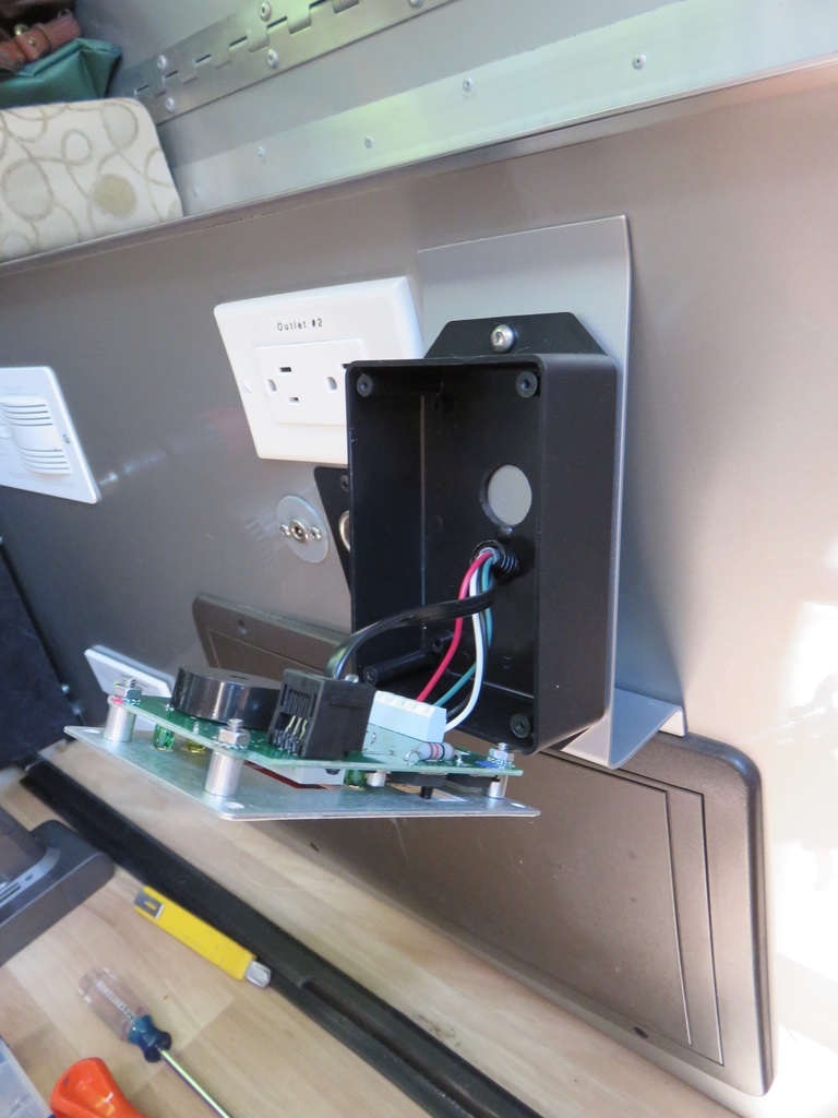
had to re-position and modify the spray shield for the remote temp sensor

In use, the switch is easily within reach by the step, and they cast just the subtle glow I was hoping to achieve. What first appears to be a simple mod, the effort is always compounded when working in the smaller confines of the Alto. Sometimes it is the price you have to pay!

2 Way Fridge Switch-Over Issue

One time last summer, when I turned on the fridge, it immediately went to ignite the propane. This was unexpected, as we were on shore power in the driveway. I cycled through the on/off process, played with combinations of this including the gas button, but it still insisted on running on propane. A quick bit of troubleshooting with the manual lead me to think there might be an issue with one of the fuses, located inside the control box.

I pulled the lower vent cover and the black control box is sitting right there. A closer inspection though, soon revealed that it has been placed right up against an aluminum enclosure that covers a bunch of electrical cables as they travel through that area. Getting access to the cover screws, let alone getting the actual cover off, proved to be an onerous task. As we were soon heading out, my Plan B became a cycling of the switches again. Luckily enough, the electrics kicked in and we were OK. Not really sure why it worked, but we were OK...for now. It functioned fine all last summer, so getting to the root cause was happily deferred.

Fast forward to this summer and all was good until the third time out. All my efforts with the switch cycling solution failed, so I figured I needed to get to those fuses. Knowing the task at hand, I wanted to get a look at how the cover was constructed, what held it in place, and how could free up some room to manoeuvre it off. A quick Google search showed me the inside of the cover, and from what I saw, there was only a small lip at the bottom that would prevent it from coming straight up and off. To get this extra room, I unscrewed the entire mounting plate that the control box sits on, from the back of the fridge. This then allowed me to wiggle the box around enough so that I could pull the cover a bit forward, then up to remove. I had to be very careful to ensure I was not also pulling any of the wiring connections and circuit board gizmos along with it.

A visual and continuity check of the fuses ruled them out as a cause. Perhaps it was the circuitry or the relay that controls the switch-over, but it was working just the previous weekend. Clearly one of those elusive to solve intermittent problems. Another cycle of the switches failed, but I did notice a brief flash from the Auto indicator light. When pushed in, the Auto selection circuit is engaged, and the light comes on. In Gas selection, the light remains off. I had first assumed this light was tied to the on/off switch, but this might not be the case. I now cycled this switch a number of times, and came to the conclusion that perhaps the Auto circuit was not being powered up and engaged. As the switch is rarely used, a little oxidation on the contacts may have occurred, impacting the circuit. Finally able to get the light to stay on, the switch-over occurred and the fridge was in electric mode. If you listen closely just after you push in the Auto switch, you can hear a tiny click of the relay that allows the A/C voltage to flow to the heating element. In gas mode, you will hear the gas solenoid valve engage, and the igniter going off.

I will be keeping an eye on this, now that I know where the real cause of the issue may well be. Now I had to put back on the cover I previously removed, but before I did, I took the opportunity to cut off the lip that was on the bottom. This will allow the cover to be removed a little easier, without having to remove the entire assembly bracket. Or so I hope.


Surge Protector

Every so often you come across a blog or forum post where a trailer owner describes a serious problem they have had with their electrical system, and usually it involves a problem with a campsite power post or electrical surge. Some of the stories are pretty wild, where a miswired electrical outlet or power surge has fried a bunch of gear in the trailer. These writers have then quickly become huge advocats of surge protection. We have run into a few dubious power posts ourselves, one time the entire 30amp outlet had been ripped out of the box and was just hanging there. That was an obvious problem, but how to protect against something that appears perfectly fine, or a surge that comes out of nowhere.

There are a couple of relatively inexpensive solutions that can be used to a least provide you with some information about the power post you are about to connect to. I have used a Kill-A-Watt meter and a polarity tester, connected to a 30 amp pigtail, that will give you an idea of the line voltage and polarity, but that's all it will do. It helps, but it's not the same as protection.

I started doing a little research into what is available for surge protection, and I soon discovered that anything listed as a surge protector, does just that, protect against surges. There are however, a number of other electrical issues that can cause you problems. To protect against these, you have to step up in features and look at electrical management systems (EMS). These cover surges, as well as low/high voltages, polarity, AC frequency, open neutral, etc. Naturally, this comes at a price, with these units easily topping $200. Some surge protectors will protect you from improper wiring, generally with a warning, but few will shut down the power completely. When you look at the investment made in a trailer, the cost difference between a basic surge protector and a more comprehensive EMS product seems pretty negligible.

The other consideration is between a portable unit or a hardwired one. A portable is just that, it plugs into the power source, and your cable plugs into it. It can then move with you when you change trailers, or also move with the thief who is looking to score a new one, or make a few bucks selling it. Need to keep this in mind when choosing the portable, and some manufacturers are now putting a locking loop on their devices. As we will never be changing trailers, I decided upon a hardwired model. The install would become an interesting little project.

Of all the manufacturers out there, Progressive Industries kept popping up as one of the best. They have a variety of models with all sorts of features, at a variety of price points. It was though, their evident pride in the quality of the product that impressed me the most. They manufacture in America, using quality components, and they back up their lifetime warranty with superb service. Many reviews I read provided stories of how they have gone to great lengths to resolve any issues as quickly as possible. Always good to hear. Another interesting feature is the plug and play replacement of the internal parts. If there is a problem, or a component self sacrifices to protect the wiring, you contact their technical support, describe the issue, and if it is an option, they will send you the component needed to get you back up and running. This is a great idea, especially for those comfortable with swapping out internal pieces. I went with the EMS-HW30C, a 30 amp model, with a remote display panel.

Now is as good a time as any for my usual little disclaimer warning. If this sort of project is not right up your alley, do not attempt it. You are messing with the AC circuits of your expensive Alto...connect something wrong, dislodge a wire somewhere, and you could cause serious damage to yourself, or the Alto. Use a portable model instead, or find someone competent to install a hardwired version for you. If you also happen to be still under warranty, well, that is yet another consideration.

Where to put it? My goal was to just splice it into the main power line, to avoid running a new cable, but this means creating some extra slack to allow for the connections. Not many places where this would be easy to do, as a matter of fact, I think there is only one place you can do this, and that is the front wall, just inside the trunk compartment. Physically it fits nicely there, assuming of course that the area is not already occupied with a bunch of caravan mover gear. The main power cable passes by along the lower edge, but now I needed to find some wire slack. I removed the aluminum cover to the front cubby, home to all things electrical in the Alto. Before doing anything but eyeballing, make sure you are not plugged into shore power...safety first! I followed the orange cable and discovered that ours had a nice big loop before it enters the distribution box, and figured with a few little changes to the wiring harness, I would be able to free up more than enough to splice the EMS into the line. The front cubby is a mass of wiring, and one needs to plan and be very meticulous when working in this area. On top of this, #10 cable is a bear to work with, and requires a lot of slow patient moves and twists. I soon had a nice loop along the front wall.

Mounting the unit was the easy part, and as always, correct selection of screw length is essential. I tend now to use a punch to create a tiny pilot hole to start the screw, as a drill bit can plow through an Alto wall like butter...and that is a very bad thing. Once mounted, off came the cover, then the cutting of the wire. First confirm everything is as it should be before proceeding. It was then just a matter of feeding the wires and making the correct connections to the terminal blocks, nice and snug. The remote display plugs in using the provided cable, and this can be placed anywhere. Some mount it inside, but it does have a continuously scrolling display of information, which perhaps might be a little annoying after a while. I chose to mount it by the EMS box, visible with the trunk door open, so I can review the information once I plug in the shore power. After that, not really much need to monitor.


Time to power up and see if anything explodes...which I know full well is not going to happen. Pretty uneventful startup. The display comes to life, runs a quick self test, then starts its never ending scroll of info. It cycles through voltage, current, frequency, error codes and previous error codes. Much like the Trimetric, it is pretty cool to see these details, and definitely reassuring to know it is in place. With an EMS, the default behavior in the event of an issue is to cut the power completely off until the problem is resolved. There is though, a bypass switch on the remote display, which allows one to shut off all the advanced EMS protection, other than the surge. They explain that this can be used in the event that something goes wrong with the internals of the device, which presumably is displayed as an error code.

Jumping ahead a bit in time, it has been in use for a couple of trips where we have had services. It has performed flawlessly, its presence relatively unknown to us. I say relative because it does make a typical electrical hum. Loud enough to be noticed inside the Alto, a low grade sort of noise that is there, but not really there unless your mind looks for it...and my mind does. It would probably not bother most people, but it is there. So naturally I started to think about how to muffle the sound a bit, some sort of insulated cover that could be placed over the entire unit. I checked to see if it generated any heat while in use, and it really does not, so a cover is an option. Thinking about materials, I decided upon getting some high density foam, of the sort that is sometimes used for knee pads in kayaks. Our local camping outfitters sells this stuff in a variety of thicknesses, and by the square foot. Perfect. I soon had created a nice soundproof box, gluing the pieces together with contact cement. Perhaps not the most attractive of solutions, but it is out of sight, and most importantly, reduces the hum to a nice silence.


Nice to know it is there keeping an eye on things, if the need arises. As a project, it was certainly doable, but it was a fair amount of work to get it installed, mostly because of the contortions needed to work in that confined front space.

Solar Upgrade Part 3: a 12 volt audit

When one gets a new gizmo, there is a strong tendency to gravitate towards using it all the time...it's only natural. I would have to say that the Trimetric has had a bit of this effect on me...I just have to press that little button to open up the new world of information it has to offer. This is not a bad thing mind you, I have a much better understanding of what is going on with the state of our solar/battery setup than I ever did before.

Once I got past the fascination with the raw data, it was time to put it to use to figure out exactly what each 12 volt device in the Alto costs, in terms of impact to the battery. Energy conservation while off grid is a bit of a pursuit of ours, so knowing what the real loads are will be great. So I began an energy audit, and along the way, learned a little bit more about how some devices actually work.

First I put together a list of the devices that run on 12 volts, or have a 12 volt component in their operation, such as the 2-way fridge. It may be propane and electric, but the overall operation is controlled by a 12 volt circuit board. Same goes for the water heater. There are a surprising number on board, 19 unique devices in our Alto, not double counting any of the similar light fixtures.  Once I had the list, I then set about to determine the amp hour draw of each one.  This involved turning devices on one at a time, and recording the draw as measured by the Trimetric.

With the display off, the draw of the Trimetric is .01 amp/hr. This came right from the spec sheet, as with no display, how would you get this info? With the display on, the draw is .03 amp/hr. This became the phantom draw to be removed from each reading taken. Next up were the detectors, of which our Alto has the two separate units, LP & CO. As they are both on the same circuit, it was easy to find the combined draw. I might add that all this detective work was done well after darkness had fallen. I wanted to completely eliminate any residual power generation from the solar panels.  The amp/hr calculations done by the Trimetric are based on what is going in & out of the battery. If there is a bit of solar amps going in, then the reading of a device’s draw will be skewed by this positive value. This also fluctuates, as the Trimetric is sensitive enough to pick up the solar output changes caused by even a tiny little cloud.  After dark, I know the readings are truly for the device draw, with no other influences.

From there, it was just a matter of putting the various devices into use one at a time, and watching the Trimetric calculate the negative impact on the battery. Pretty straight forward stuff, or so I thought. I had assumed that once the detectors were on, that was the draw. Not so. While I was finding the draw for one of the LED lights, I saw the amp display move from a stable value, and jump up a fair bit.  There was nothing else on, other than the detectors, so it was a tad puzzling. A bit later, the draw dropped back down to what it was when the light went on.  I turned the light on and off, and monitored the draw further...sure enough, up it jumped again. I timed the on/off cycles. It was soon clear that one of the detectors was "sniffing" the air on a regular 1 minute on, 1 minute off cycle. Based on this, the phantom draw of the detectors was certainly more than I first recorded, and you would be surprised how this changes the calculations over a 24 hour period. The fridge has a cycle as well. There is the control board, and then when the fridge is called upon to cool, there is a little solenoid that opens to allow the propane to flow for the cycle. Holding that solenoid opens makes up the bulk of the draw, and needs to be factored into the amp/hr cost.

Once everything was mapped, I created a little spreadsheet (of course) that would calculate the draw of each device, over different periods of time. Anything with a phantom draw as well as a functioning draw is calculated over a 24  hour period, and this required some adjustments to blend the amp/hr rate. Yes...this is all very geeky.

The chart is pretty interesting, especially when you start to play with the amount of time that a device is running in a day. Take the water pump, a huge amp hog, but then look at how long it actually runs in a day. Even including the possibility of a Dale outdoor shower, would that pump run 10 minutes, 15 perhaps, in a day. This works out to about 1 amp/hr a day. Now look at those little detectors, no motor in them, yet over the 24 hours they are on, they eat over 3 amp/hrs! Now who is the power hog??? But that's not to say those are not worthwhile amps, and certainly not going to try to save any there.

When trying to figure out just how many amps were being used in a day, I think there are a couple of groups, what I call the driveway and camping core draws. These are consumptions that are just simply going to be there, regardless. The driveway consists of the Trimetric and the detectors, and over a 24 hour period, adds up to over 3 amp/hrs. I've heard some people pull the fuse on their detectors at times, but I'm just not comfortable with that, even if it is just simply sitting there, waiting for the next adventure.  The core camping draw are the same devices, but adds in the fridge and water pump. If you are out, you are pretty much using these, and they are pulling amps out of the battery. I'm sure you could find some savings if you are able to adjust the temp of the fridge, or even turn it off, but for the sake of not getting too crazy with the calculations, I'm assuming a relatively normal manner of operations.

From there, I used this core group and came up with a couple of scenarios, to try and estimate just how much we may be using. These definitely lean towards conservative consumption. You can see how it could be very easy to use up all your available amp hours, as devices go on, it add up quickly. If you are out for a while off grid, you also have to keep in mind that you need to replace the amps you take out, and this requires good solar conditions...which means lots of sunlight. As well, from what I have read, the amp hours come out of a battery a lot easier than they get replaced, which is probably the main reason I upgraded the solar controller, to make sure this process was as effective as it could be.

So after a few outings with the new solar components, am I satisfied it has been a good investment? Most definitely! Not only do I know exactly what is coming and going from the battery, I know that the battery is being charged as effectively as possible. Can I quantify this. I think so. The battery recovers its charge a little faster, from the parameters programmed in it is certainly fully charged, and when I initiate an equalization phase, I know I am prolonging the overall battery life as per Trojan specs. Sounds pretty good to me.

I would certainly recommend the additional of a Trimetric monitor for those planning on a lot of off grid camping. It really helps you know exactly what the battery state of charge is.

Have a look over the chart, and although some of the equipment in the Alto has changed over the years, it will give you a high level picture of how amp hour usage can accumulate over the course of a day, and how your own camping style will impact this.  The raw numbers are there to help you calculate your own scenarios. Pretty interesting stuff.


Item Device Phantom
Draw
Amp
Draw
Approx
Mins
Day
Approx
Hrs
Day
Daily
A/hrs
Notes
1Trimetric
(display off)
0.0100.010144024.000.240
2Trimetric
(display on)
0.030300.500.015
3LP/CO detectors
(individual units,
same circuit)
0.09
(0.18 sniffing)
0.135144024.003.240- one detector sniffs for
1 minute,
then phantom for
1 minute
- amps prorated
over 24 hrs
4Fridge
(Dometic
2-way propane)
0.07
(0.32 cooling)
0.284144024.006.816- estimates fridge cools approx. 40 min/hr
 -amps prorated
over 24hrs
5Fridge Vent Fan
(single 50CFM fan)
0.1703005.000.850- only used during
hot weather
6Water Heater
(Suburban propane)
0.750300.500.375- morning/evening
cycles
7Furnace
(Propex propane)
2.1701803.006.510- morning/evening
occasional cycles
8Water Pump5.630100.170.938
9Roof fan
(setting 1)
0.9601803.002.880
10Roof fan
(setting 2)
1.4901202.002.980
11Roof fan
(setting 3)
2.240000- rarely used
12Roof lifts6.03010.020.101
13Bench lift1.16010.020.019
14Light fixture
(single LED
tube retrofit)
0.420601.000.420- Luci lights factor
into all lighting estimations
15Light fixture
(double LED
tube retrofit)
0.910- rarely used
16LED strip
(front cabinet,
dimmer low)
0.030601.000.030
17LED strip
(front cabinet, dimmer high)
0.270
18LED strip
(sink)
0.150300.500.075
19LED strip
(ceiling ambient)
0.220601.000.220
20Exterior light
(incandescent)
0.930- rarely used
21TV
(tv mode)
0.050
22TV
(dvd mode)
0.0501.7501202.003.50
23Tank monitor0.13020.030.004
24Fantastic fan
(portable,
setting 1)
1.3301803.003.990
25Fantastic fan
(portable,
setting 2)
1.980
26Fantastic fan
(portable,
setting 3)
2.760
27Tivoli
(radio charging)

28Core draw
(driveway)
0.145144024.003.480- items: 1, 3
- amps prorated
over 24hrs
29Core draw
(camping)
0.429144024.0011.234- items: 1, 3, 4, 8
- amps prorated
over 24hrs
30Cool day scenario18.644- items: 6, 7, 14,
16, 18, 29
31Hot day scenario22.834- items: 5, 6, 9, 10,
14, 16, 18, 24,
25, 29
32Conserving day scenario 14.114- items: 9, 29

Solar Upgrade Part 2: the install...

Lots of moving parts to this mod, and right up there on a par with the brain cramps experienced solving the furnace dilemma we had a few years back.

As I have mentioned before, do not attempt any sort of mod, or maintenance for that matter, if you are not totally confident you can do it right. The posts I have on our blog are not instructions for you to follow, just simply a recollection of stuff I have done to our Alto. When in doubt, get it done professionally. There...disclaimer over.

Where to start, although that is a bit of an odd statement given I have probably done the mod a dozen times already...in my head. One has to be extra careful with a mod that could bite you hard if it goes off the rails, and believe me, I am super dialled in when working on these ones. I figure the best way to go about it is this one is to do the outside changes first, namely the shunt installation on the battery and the new wiring, then install the Trimetric monitor and get it running, then tackle the charge controller part. This last part involves working in the close confines of the front battery compartment, which is hidden under that long front cushion, and making the switchover of the wiring and components. So this will be the order that I describe my steps.

Battery Box Work:
The Trimetric needs to monitor any voltage changes that occur across a shunt, which is a component that is installed between the negative battery terminal, and the negative load wires. When electricity flows across the shunt, minute changes in voltage are captured, and the monitor performs calculations to figure out the amperage flowing in either direction. It also monitors the voltages present between the positive and negative terminals, very accurately. The shunt is attached to the negative terminal, and this is usually done with a very short piece of really low gauge wire. In my situation, I only have the area on top of the battery to work with, so I decided to fabricate a copper connector to attach the shunt directly to the terminal. This involved bending a short piece of 1/8 inch copper bar, using my handy dandy bending brake. A couple of mounting holes later, and as you can see from the photo, it sits there quite nicely. Also visible is the new terminal fuse, a nice solution when there is limited space to work with.


The topic of fusing came up all the time, and particularly, the overall lack of it in the RV world. I decided to add fuses where research told me they generally should appear. This includes a fuse on the positive terminal. There is already a fusible link installed as part of the positive cable. This is a "slow burn" type of fuse, designed to melt away when an over amperage occurs. This is probably to help accommodate a brief high amperage situation, such as when an inverter starts up. I decided to add a high amp terminal fuse to the equation, as an extra layer of precaution. Blue Sea Marine make excellent electrical products, which I found at my local chanderly outlet. If you ever get a chance to wander the aisles of a marine outfitting store, definitely do it. There are lots of crossover products between the two industries, and I would have to say, the marine parts are of a very high quality.

Wiring:
I sourced the wire at the marine outlet. They have the Ancor brand, and it is really good stuff . Overkill, but not that much more expensive than the welding wire generally used for this purpose. These wires also needed lug ends, so I got a bunch of those as well. This raised another issue, how to crimp the ends. Fancy crimpers cost a fortune, definitely not worth the expense for a handful of necessary crimps. Again, You Tube provided a number of home grown solutions. I was soon able to crimp, and then solder my lug ends. Soldering added just that extra layer of protection from the lug coming off, but frankly, my crimps were pretty effective to begin with. Some adhesive lined heat shrink tubing completed the job. I also took the opportunity to redo the lugs on the existing wiring, as there were starting to show a little too much flex at the joint. Damn fine looking end result if you ask me.


Now to run the wires. I determined that the existing plastic wire wrap would not hold the two new wires, so I ran these in their own wrap. I was able to follow the existing wires along the frame channel, then drilled a new hole through the floor up into the electrical compartment. This wire wrap also contained the cable running from the shunt to the Trimetric, as well as the wire from the temperature sensor that sits in the battery box. Other than crawling around under the Alto, and the pain in the ass it is to remove the spare, it was a simple job.


The Monitor:
Now the cool stuff begins. The monitor is installed on the bulkhead wall beneath the front table. I fashioned a nifty little bracket, to push the bottom of it out from the wall just a bit. I figured this will make the monitor just a little easier to see and use. A few holes were drilled, and the next thing you know, we had wiring out to the monitor. I then made the connections to the shunt in the battery box, then to the monitor, put the little fuse in place...success! The Trimetric was alive.

just a few extra connections here


the little bracket actually makes quite the difference when viewing and using

The Trimetric is a nice piece of engineering, but it does have a very complicated programming side to it. In fairness, after setting up three parameters, you can be off to the races. However, people buying this particular piece of kit are more interesting in programming the hell out of it. In a world full of simple user interfaces and mouse click convenience...this thing is old school. Not only is there the challenge of understanding of what the parameters mean, inputting those parameters is a primitive process. It does though invoke a reassuring sense of function over form. While it may not be friendly to program, the sophistication of its capabilities is very apparent, and in reality, that is why it was purchased in the first place. Even the language of the instruction manuals is very functional and to the point. No tech writer has polished this text for the masses, and did require several readings just to begin to understand what was going on.

As the controller was not yet installed, I just performed the basic set up, and let it monitor away. Right off the bat I was enthralled by the information it was gathering and outputting. Enthralled might seem a bit strong...but for the longest time I was mentally kidnapped by the glow of its flickering numbers.

The Rest:
Lots of odds and sods to this part. Panel combiner, controller, fuse holder, wiring...those little changes never seemed to end. Also, I wanted to do this after dark, to minimize the output of the panels. I remember saying to Dale that I had about another hour of work to do...boy did I ever under estimate that!

First I had to take the existing controller out of the picture, and that involved disconnecting the panels, then removing the controller from the front wall, to free up that needed space. As well, I then had to remove the existing wiring that connected the controller output to the distribution panel. This is where I discovered something that seemed a little out of the norm. During my research, in all the photographs or wiring schematics I had viewed, I had never seen the controller output wires go to any location other than directly to the terminals of the battery. In the Alto, the controller output was going to the distribution panel, through a 15 amp fuse. Clearly it works electrically, but is it the most effective method...that might be debatable. To me, it's like having those precious electrons take a rather meandering route to the battery. Does it really make a difference? That depends on how you look at it.  I decided to follow what seemed to be a more common approach, and wired the solar controller output directly to the battery, through a fuse of course.

Next I needed to mount the solar combiner, the new controller, and the new fuse block. I am using a Blue Sea ATC fuse distribution block as a solar combiner. On the roof of most solar installations, the panel wires feed into a combiner box, get consolidated into positive and negative wires, then make their way to the controller, usually through a fuse. Our combiner is installed by the controller. Each panel is now fused, which provides a level of protection from each other, should one ever short circuit, and from the other direction should the controller ever go all willy nilly. I can now disconnect the panels from the solar circuit altogether, and I have lots of room to accommodate additional panels in the future. From here, the combined output goes directly to the controller, using the larger 6AWG wire.


The controller was installed and the combiner wires connected. On the output side, the negative wire goes directly to the Alto side of the shunt on the battery, so that the monitor can keep track of the solar input getting to the battery. The positive wire first passes through a MAXI fuse block on its way directly to the battery positive. The fuse block provides another layer of protection between the controller and the battery. All this is based on my view of what I think are some of the better solar installations that I have seen. I may have a bit of overkill here, but no harm done.


Final connections at the battery, and we are ready. One problem though, it is now pitch dark, and the solar is producing nothing. I left the combiner fuses out, and waited until the morning to see if the whole shebang actually works.

Next morning the fuses went in, the panels were already producing power, the controller was talking to the monitor and sweet electrons were flowing to the battery. Nice!

Now to fully program the Trimetric to manage the controller. Not to go into it completely (those really interested can download all the Trimetric documentation) but essentially you program the Trimetric monitor to manage the charging performed by the controller. Remember the concept mentioned earlier about tailoring the charging profile to the manufacturers specs, this is the time where that comes into play. Bogart has made this a little easier by creating several built in profiles that will populate the parameters needed, based on the different manufacturers specs. I found the Trojan 12 volt profile, and input it where required. This then populates the various charging voltages, amperages and timings accordingly. I discovered on the Trojan site that each of their batteries can have different charging specs, so I downloaded the spec sheet for our battery, and then fine tuned the parameters as needed. Trojan Battery has an excellent web site, and it is used as a knowledge base by many.

As the Trimetric can communicate with the controller, there is a smorgasbord of solar charging information available to monitor and review. I now know exactly what charging phase the controller is currently in, in addition to being able to know exactly the amperage output of the panels themselves. That is just the tip of the information iceberg. One of the first activities I will be doing as well is an energy audit of all things 12 volt. From this, I can then better guess at what our daily power consumption really is, and who the energy hogs are.

At the end of all of this, we now have a solar set up that monitors and charges our battery exactly to Trojan specs. Naturally there are variables, such as the hours of solar available in a particular day, but overall, I know that our new solar charging system will do a far better job of completely charging our battery than our grid power converter can. I see leaving it off grid power at home the majority of times, and letting the solar do its thing. Plugging in the night before we leave, to get the fridge cool using energy from the grid, will most likely be one of the rare times the Alto will be connected.

This mod ties in nicely with our future travel plans, where boon-docking will play be a big part. Even the past few years we have found ourselves preferring sites with no services, as generally, these are on the water, to us, a very desirable location. We have given ourselves excellent solar charging capabilities, and have ensured that any future expansion, however limited that may well be, will also be nicely accommodated.  This was a fun project, and right up my alley, because for me, the Alto is not only about camping, it is also about modding, which is definitely a big hobby of mine.

Part 3 of this saga details the energy audit for our Alto.

Solar Upgrade Part 1: solar musings...

This is a long post...two parts actually. It is pretty much my thoughts based on a winter of analysis, trying to figure out how to best manage our future solar requirements. Do any sort of reading on solar power for RV use and for as many manufacturer articles and personal blogs you find, you will find a similar number of opinions. You really have to separate the wheat from the chaff to get at what is best for you.

As retirement is just starting to peek over the horizon for Dale and I, we find ourselves thinking more and more about how we will spend our time. A lot of that thinking is centred around how our Alto will figure into these plans. I have to admit, the places to visit and sights to see are mostly coming from Dale's planning. A good part of my planning, quite naturally so, is centred around how to make sure the Alto best meets our travel and campsite needs. We knew pretty quickly that the Alto would be well suited for us, from a design, usability and comfort perspective. Safari Condo has put a lot of thought and effort into making this a great product right out of the gate...and it certainly is! Over time and use though, we have been doing a few things to make it just a little bit better for us. I think most owners do this. Nothing big really, just stuff that we want to add, mods we make, that sort of thing. So we have been reading and following a number bloggers, ones that seem to either resonate with us from a travel perspective, or those that perk my interest from a technical bent, all towards gathering information for the future.

I've been reading a lot about solar power. A LOT.  Focussed primarily on RV applications, but also general knowledge. Scratch the surface on this topic, and you will find there is much more than just panels and batteries. There is the theory, the various types of components, and of course, the abundant opinions. So as I kept discovering new sources of information of the topic, I found myself gravitating to those that just seemed to make the most common sense to me. The key is finding that balance. There are lots of solutions out there that are just so enticing...the lure of the lithium battery, the wattage available with newer/more panels. All this dreaming comes at a cost though, both in terms of monetary and effort outlays. It is very easy to be led down the garden path towards someones idea of boon-docking nirvana. Sanity must prevail. Personal needs must be determined, and those are different for everyone. Spend too little time figuring this out, and you may find your wallet a lot thinner than it really needs to be.

I sifted the info, contemplated the sort of camping we would be doing, and tried to come up with an overall solar plan to best meet our needs. At this point, we don't anticipate the use of an inverter, so that will certainly factor into our required capacity. There are those that certainly do need to use an inverter, but I am confident our solar planning will support this in the future, should the need ever arise. So just where have I ended up after this information overload. I like to think I have figured out our anticipated needs as best I can, bounced my ideas off poor Dale, who in fairness, has tried her very best to not fall quickly asleep listening to my technical ramblings. I can get pretty focussed when I become interested in a topic, especially one that can easily morph into a hands-on project. As well, based on our off-grid experiences of the past few years, it seems we don't really need to throw a lot of money at this to see an improvement. Going the lithium route to gain amp hour capacity, now that would be some serious coin, and probably not really necessary for us. I think this is one of the key decisions for those contemplating the same sort of analysis. Lithiums do take you do a bit of a different path from an equipment perspective, and it requires some serious thought, and a fat wallet.

What will our setup look like? Well, no acres of panels, no expensive lithiums, no inverter sucking the life out of our battery, and certainly no configuration to support air conditioning. Don't be thinking for a moment though that if it got stinking hot while we were in the middle of nowhere, that we would not be pulling up stakes and heading towards the nearest full service park...to plug in and crank that A/C up full.

Another big influence over the solar improvements available to us were the limitations imposed by the Alto itself. We don't have a lot of space to work with. We are somewhat panel limited by a small and unique roofline, and we are battery limited by a tiny and already well utilized tongue area. There are the possibilities of external panels, or lithiums inside, but both of those would impact our storage space, in the tow vehicle and the Alto. There is no way there will ever be a line of Trojan T-125's residing on the tongue, as excellent as that would be, but it is just not feasible. I have recently heard of one Alto owner almost covering the roof with panels, and it looks pretty impressive, but just what are they charging with those watts of power? Perhaps a big bank of lithiums, but that brings us full circle back to that space concern. Who knows what the future might hold. If our panels have an issue down the road, we would probably take the opportunity to add an extra panel, and maybe throw on an extra battery...but right now...that's not in the cards.

So what are the core concepts of our plan? Well, kinda straight forward really:
- the panels we have
- a good monitor & charge controller
- improved wiring
- true deep cycle battery
- energy efficiencies

Let's bounce around some thoughts on these:

Panels:
There are a number of general ideas floating around out there that try to provide a guide as to how to size your solar array, and what is needed to recharge a battery bank. Figuring out what, or who to believe definitely takes some thought. I went with the guides that seemed to be logically defined and explained, and ultimately, just simply made sense to me. It is said to have a panel array output wattage relatively equal to the 20 amp hour rating of your battery bank. Seems reasonable. As well, given an average of the effective solar generating hours in a day, and this will certainly vary a lot, you should have at minimum from 3-6 % of your total battery amp hour rating available in charging amps, to even hope to recharge your battery bank.  This is perhaps a a little tougher to quantify, but these same numbers came up a lot. I'll go with this.

We have two 68 watt panels on our Alto, wired in parallel, for a combined output of 136W / 16.5V / 8.2A. These are the specs based on testing at what is referred to as STC (Standard Test Conditions), and really only represents perfect world lab conditions. Looking at the other set of specs, based on NOCT (Nominal Operating Cell Temperature) and the numbers are certainly different at 106W / 15.4V / 6.84A. This second test is meant to mimic actual conditions, so perhaps reality is somewhere in between. Either way, real output is less than the glossy brochure says. Crunching some numbers made me realize that even though we have a relatively modest panel watts/amps, we should be OK from a charging perspective. One also has to keep in mind that you are really only recharging half your total amp hour capacity, given that you should not run down your battery to below 50%. So what would I do with a roof covered in panels, I'm not really sure. Certainly would speed up the charging times, but I suspect we will be just fine as is.

Monitoring:
To really know what is going on with your batteries, you need much more than those idiot lights or a simple voltmeter. You need accurate voltage readings, and a way to keep track of the amps/watts being consumed and then replenished back into the battery. To get this, you need a good monitor, and also a shunt. These two work hand in hand to provide information back to the user. General consensus out there seems to be that the Trimetric brand, made by Bogart Engineering, is one of the very best of monitors available. It can provide all sorts of key information back to the user, and this information can be adjusted based on the geekiness of the particular user. Ours will be set up for maximum geek.

Charging:
Now here is a very interesting aspect of the whole solar equation. Opinions run pretty fast and furious here, not only from the user community, but also from solar equipment manufacturers and retailers. Lots of statements get bounced around..."Get an MPPT controller because it boosts the output of your solar panels". Do you know why, do you have the whole story, does it apply to your solar setup? And the list goes on. This is when you need to continue to read, develop your own opinion, and apply it to your needs. In a nutshell, it seemed to boil down to a couple of things. The type of controller to use...PMW or MPPT, which one could argue is really decided for you based on the output specs of your panels, and whether you feel the controller will be charging your battery effectively?

From what I have seen and read, solar controller manufacturers do not seem to be optimizing the phase charging voltages according to battery manufacturers specs. This does impact the efficiency of a controller to truly bring the battery to a full charge. In most cases, it is very much a one size fits all situation. Does generic get the job done...perhaps. Do the majority of end users really care...probably not. Regardless of the PMW/MPPT debate, it seems to me that a key requirement for a controller is to provide the ability for user adjustments to the phase voltages, to bring this in line with what a battery manufacturer recommends. After all, who best to spec those details. Exactly! And by the way...phase voltages are just one part of the equation, there are a few others that matter as well, such as current output and charge times, but volts always turns up as the first discussion point. To top it all off, controller manufacturers are not the only ones lacking this flexibility. When you plug into grid power, that converter is likely not optimized to charge effectively either...and some don't even provide phased charging. It's kinda like never totally filling the gas tank on your car before a big trip...why would you not do that? To me, good controllers are adjustable, and sophisticated enough to utilize charging parameters to best ensure the battery is operating at full capacity. If I'm limited by the amp hours that I can carry with me, and we are, then I want to make damn sure I have as many of those available for use as possible. What controller to get...one that I can adjust to suit the battery I am using, even if I change it out down the road.

Wiring:
Small gauge wires can impact your charging efficiency. Simply Ohm's Law. The more resistance in the wire, the less voltage/amps getting to the battery. Smaller wire equates to greater resistance...and this is definitely a direct current specific statement. General rule of thumb is to have as big a wire as possible between the output of the controller and the battery terminals. In a perfect world this would apply to the entire solar circuit, but in reality, that is sometimes hard to achieve. Pretty hard to run a 4 or 6 AWG wire up to the panels on the top of the Alto...now that would be an interesting challenge. So in that case, maximize the wire where you can. There are wire gauge tables out there that will tell you the recommended length for each gauge of wire, to keep any voltage loss below a 3 percent maximum. Does any of this really matter.  Yes...and no. If you have gobs of panel wattage and battery amp hours, probably not. But if you are trying to eek out as much power as you can from a modest solar setup, then I am of the opinion it certainly can't hurt.

Battery:
Another very opinionated topic. Flooded, AGM, Lithium...how to decide??? Easy..research and buy to suit your needs, and wallet. Of late, I have been fascinated with the promise of the lithium battery. They sound like an ideal overall solution. Awesome usable amp hour capacity, compact, relatively lightweight, simple charging profiles...this all sounds ideal. What do these wonders cost? "Really...wow!".  As with most new innovations, the early days are the most expensive. Crazy expensive. Now before you bring out your calculator and start rhyming off cost per amp/hour numbers, the bottom line is that right now, to me, they represent a tremendous outlay. And it is not only for the batteries themselves, the charging and battery management components that are required go for a princely sum as well. Now if we were going to be full timing, then the benefits might well outweigh the sticker shock. I gather the lithiums are a bit temperamental as well, and do not peak performers in hot temperatures. That is why you will rarely find them installed in battery boxes on the tongue of a camper. This means they would be inside the Alto, and that means giving up storage space.

We needed to replace our original battery last year, which was a Marine/Deep Cycle group 27 unit. I did a little research and went with a Trojan 12v deep cycle battery, in a group 31. This has increased our amp hour availability somewhat, and it is what I am calling a true deep cycle style of battery, where the design considerations are more based on charge/discharge cycles and amp hour capacity, rather than the need to crank over an engine. I had contemplated going the dual 6 volt battery route, but decided to wait and see how this new one would perform.  We also want to get a year or so of retirement trips with extended boon-docking under our belts first, to really give us an idea of our true needs.

Energy Efficiency:
How conservative you are with the amp hours available to you will directly impact your boon-docking time. Run an inverter to make popcorn in your microwave, or watch movies all weekend (we've been there, suffered the consequences) and you will find yourself with a dead battery. It is no fun when your propane fridge shuts itself off because it has no power to meet the 12v requirements...and that is a pretty minimal draw. We won't even get into a debate on the merits of the 12 volt compressor fridge over a propane...that's another hot topic. For the record though, I'm in the propane fridge camp, and actually, quite happy to debate that.

You can do all sorts of things to conserve power, and it certainly does not mean you have to sit there in the dark like a couple of moles. Switch to LED lighting, if you do not already have them. We did, and beyond the energy efficiency, we really like the warmer colour tone of the light they provide. Become aware of your power usage, figure out your power priorities. First thing that jumps to my mind as a priority is the fridge. I'll take a cold beer over a bag of microwave popcorn any day of the week! I guess you could say it all boils down to living within your amp hour means, and a factor in that is definitely how well you can recharge that battery. We find that after draining our battery a couple of years ago, we have become very power conscious when off grid.  We have boon-docked for a couple of weeks solid, and so far, have not had any real power concerns, and we are hoping this little upgrade will help our overall solar system.

So after this rather lengthly rambling, where does that leave us. With this:
-Trimetric setup
-Improved wiring (and fusing!)
-True deep cell battery (already in place)

The general idea is to swap out the existing charge controller for a Trimetric SC-2030, and manage it with a TM-2030 monitor. These pieces were designed to be used together. New wiring from the controller directly to the battery will be 6AWG in size, and fusing will be added in appropriate areas of the solar circuit. All this in the hopes to maximize the charging and storage abilities of our rather modest solar setup.  Even in the future, I can't see changes going much beyond this new setup. Perhaps an extra panel, perhaps another battery, but that is about it. I might also say that this could be termed a reasonable upgrade, specifically in terms of a monetary outlay.

Part 2 of this will detail the work involved to put all the pieces in place, and it was a fair bit of work.

Refrigerator Fan

There is a lot of discussion out there regarding the cooling efficiency of a propane absorption RV fridge. Some people have reported having difficulties getting the fridge to cool enough, especially if it is very warm outside. Overall, we have not had any cooling concerns with ours. An addition that apparently helps the fridge cool, is a small fan, installed behind the upper vent cover, above the top evaporator grid. The theory being that if you help the natural convection along a bit, the fridge become a little more efficient, and the cooling increases.

Safari Condo now has a fridge fan option, but being early adopters of the Alto, it was not on our option list. As I like modding, this became a nice little project. Even though we have had no concerns, there are times when that side of the Alto has been in full sun, so it would be helpful to be able to switch a fan on when needed. Not many parts needed…a fan, usually a 12v computer fan, a fuse of some sort, a switch, and some bits and bobs of wire and aluminum. At our local electronic parts store, I found a suitable fan, 120x120 mm square, ball bearing spindle, moving 70CFM. I also picked up a lighted rocker switch, as I want to know at a glance that it is running.

One change that SC has made on the fridge install is the addition of baffles inside the fridge enclosure. This is to help direct the airflow outwards. Looking at ours, without the baffles, there is a lot of dead air space, which can trap warm air. We have noticed that the inside of the little cabinet behind the stove can become quite warm, so I suspect the baffles will help that a bit. I fashioned the baffle out of thin galvanized sheet metal, that I found in the HVAC section of Home Depot. Standard stuff. My baffle install is not as fancy as the factory’s, but it serves the same purpose.

Next was to mount the fan on a piece of L aluminum, then this was screwed in place above the evaporator grid. I tapped into the 12v terminals for the refrigerator, and fished the wire up towards the fan. Next I drilled the hole for the switch, right beside the 12v plug I installed a few years back. Located here, it is out of the way, yet still visible enough to see that the switch is lit and on. A bit of wiring, including a low amp fuse in the circuit before the fan, so if something goes screwy with the fan, this fuse will blow first, and not impact the power feeding the refrigerator.


Re-installed the main refrigerator fuse, always wise to cut any sort of power, and flipped on the new switch. On went the indicator light, and on went the fan.


There is a nice little breeze being produced, so it should do the job. There is a bit of a noise as it is running, but not too noticeable. For the times it will be actually. In use, I figure the roof fan will also be running, which will mask most of the noise.
running...but you'll have to believe me
Put the cover back on, and the air was moving nicely through it. It will be interesting to see what sort of impact this fan has on the operation of the fridge, but regardless, it was a fun little project. In terms of costs, it was probably about a $30 dollar job, with a time investment of about 3 hours...most of that running back and forth to the basement when I forgot to bring a tool or something back with me. Always happens.