Ever fumbled around on the floor while peering into that dark pit of the fridge, trying to find that perfectly frosty beer? I have many times, and it is not fun. It has always crossed my mind that a light would be so damn handy.

On our recent trip, I happened to watch as Angela opened the door of the fridge in their 2114. A wonderful shade of blue bathed the interior and guided the way to the goodies inside. Dale turned to me and immediately said that we needed some sort of light in our fridge. A mod started to percolate.
Our fridge is the Dometic RM2351 two-way. A basic absorption fridge with nary any bells and whistles, although it is a solid performer. Surely some sort of light could be added. The parts list would be pretty basic…a small strip of adhesive LED lights, a switch, some wire, and electrical doodads to connect it all together.
I pondered a classic install. Door opens, light goes on, door closes, light go off. The logistics of this were another story. Not wanting to turn the unit into a Frankenfridge, with switches and wires running all willy nilly everywhere, I opted for what turned out to be a relatively simple mod.
Yes, a simple mod, assuming of course that you have a basic knowledge of 12 volt electricity, are somewhat handy with a drill and wire crimpers, and can figure out where I am going with these steps.
Two screws remove the front control panel, or as the piece is called in the Dometic parts list…the “Front Decoration-Black”. Just to the right of the door latch is a perfect area for a switch. Removing the little circuit board will give you unfettered access to the panel, as you will be drilling a hole to hold the switch. Wanting to know whether the LED’s in the fridge are accidentally left on or not, which is kinda hard with the door closed, I used an illuminated rocker switch. A quick glance tells me the status of the inside lights.
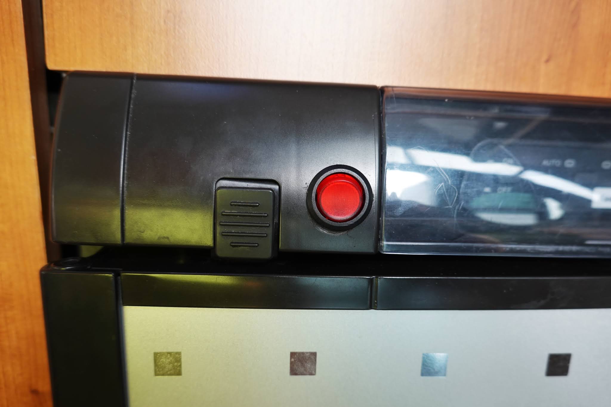
An illuminated switch requires 12v positive and negative feeds. A 12v positive output wire then travels from the switch to the positive of the LED strip. I found it the easiest to have about a foot of wire attached to the switch terminals, then do the final wire connections after the switch is installed in the panel. Make certain the wires are snugly connected to those terminals on the switch. Small female spade connectors work well, although may need to be squeezed to ensure a snug fit.
I wanted the LED strip to be close to the front edge of the cabinet. This allows the angle of the light to clear the lower edge of the freezer compartment, as best it can. When you remove the panel, you will see that there is an empty area above, perfect for running the required power feed. In fact, you will see how the cable for the front panel circuit board heads towards the back of the fridge. Just follow it with your new wire.

You will need to stick your LED strip in place, and to ensure a good bond, wipe the plastic cabinet area with an alcohol pad. Drill a hole up through the top of the cabinet, to pass the LED wires through. There is a metal front frame to the fridge, but if you drill slightly further away from the front edge of the cabinet, the drill bit will miss this frame. Go slow with the drill as you are just going through a bit of plastic and some styrofoam.

Now run the 12v power feed wire from the top of the fridge to the back, scoot around the edge of the baffle, then feed it down to the 12v terminal block. I find the best wire to use is red/black zip wire, 16 or 18 gauge is fine. The colours help keep the polarity correct. I also like to use some aluminized ducting tape to stick the power feed wire to the sides of the fridge enclosure. Connecting to the terminal block is a step we will come back to.
Back inside, connect the 12v positive of the power feed wire from the terminal block, to the positive input wire from the switch. Connect the 12v positive output wire from the switch to the positive wire of the LED strip. Then connect the negative wire from the switch, along with the negative wire of the LED strip, to the negative wire of the 12v power feed wire coming from the terminal block. All this wiring is contained within the space above the fridge that was exposed when you removed that panel.
Once all the wires are connected, you can re-install the small circuit board to the panel. Leave it all exposed until you test the light.

Add an inline fuse holder to the positive wire of the power feed. A 1 amp fuse is plenty. On the terminal block, you will want to determine which is the positive and the negative connections. You will do this with a volt meter. I could tell you how mine is wired, but that is not to say that yours will be the same. Touching the screw terminals with your volt meter probes will soon give you the answer. Before connecting the power feed wires to the terminal block, pull the fuse for the fridge. This helps avoid any accidental grounding, and frying of the fuse.
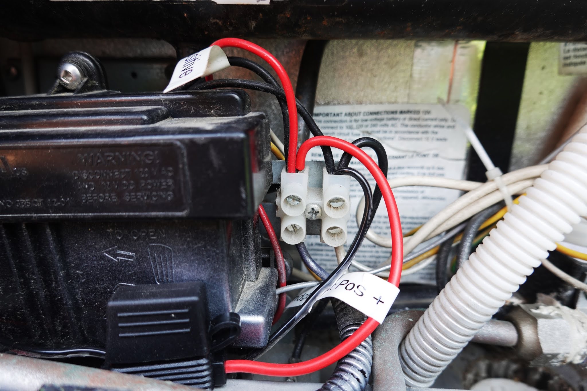
Loosen the screws one at a time, and connect the positive and negative power feed wires. These will fit in nicely with the wires that are already there. Tighten the wires and you are done. Replace the fridge fuse you earlier removed.
Now give that rocker switch a go. If all went well, that switch, and the LED strip should light up nicely. If not, go back and walk through the installation again. One possible problem area may be the correct identification of the little terminals on the rocker switch. There are three of them. Generally, one of the outer ones will be positive power in, the middle will be positive power out, and the other outer terminal will be negative. The continuity setting on your voltmeter will help you with this identification.


A relatively simple mod, if you are careful with the steps. The light makes a huge difference, as I just know you will agree.
Time to crack that frosty beer as your reward.

0 comments:
Post a Comment