As I have mentioned before, do not attempt any sort of mod, or maintenance for that matter, if you are not totally confident you can do it right. The posts I have on our blog are not instructions for you to follow, just simply a recollection of stuff I have done to our Alto. When in doubt, get it done professionally. There...disclaimer over.
Where to start, although that is a bit of an odd statement given I have probably done the mod a dozen times already...in my head. One has to be extra careful with a mod that could bite you hard if it goes off the rails, and believe me, I am super dialled in when working on these ones. I figure the best way to go about it is this one is to do the outside changes first, namely the shunt installation on the battery and the new wiring, then install the Trimetric monitor and get it running, then tackle the charge controller part. This last part involves working in the close confines of the front battery compartment, which is hidden under that long front cushion, and making the switchover of the wiring and components. So this will be the order that I describe my steps.
Battery Box Work:
The Trimetric needs to monitor any voltage changes that occur across a shunt, which is a component that is installed between the negative battery terminal, and the negative load wires. When electricity flows across the shunt, minute changes in voltage are captured, and the monitor performs calculations to figure out the amperage flowing in either direction. It also monitors the voltages present between the positive and negative terminals, very accurately. The shunt is attached to the negative terminal, and this is usually done with a very short piece of really low gauge wire. In my situation, I only have the area on top of the battery to work with, so I decided to fabricate a copper connector to attach the shunt directly to the terminal. This involved bending a short piece of 1/8 inch copper bar, using my handy dandy bending brake. A couple of mounting holes later, and as you can see from the photo, it sits there quite nicely. Also visible is the new terminal fuse, a nice solution when there is limited space to work with.

The topic of fusing came up all the time, and particularly, the overall lack of it in the RV world. I decided to add fuses where research told me they generally should appear. This includes a fuse on the positive terminal. There is already a fusible link installed as part of the positive cable. This is a "slow burn" type of fuse, designed to melt away when an over amperage occurs. This is probably to help accommodate a brief high amperage situation, such as when an inverter starts up. I decided to add a high amp terminal fuse to the equation, as an extra layer of precaution. Blue Sea Marine make excellent electrical products, which I found at my local chanderly outlet. If you ever get a chance to wander the aisles of a marine outfitting store, definitely do it. There are lots of crossover products between the two industries, and I would have to say, the marine parts are of a very high quality.
Wiring:
I sourced the wire at the marine outlet. They have the Ancor brand, and it is really good stuff . Overkill, but not that much more expensive than the welding wire generally used for this purpose. These wires also needed lug ends, so I got a bunch of those as well. This raised another issue, how to crimp the ends. Fancy crimpers cost a fortune, definitely not worth the expense for a handful of necessary crimps. Again, You Tube provided a number of home grown solutions. I was soon able to crimp, and then solder my lug ends. Soldering added just that extra layer of protection from the lug coming off, but frankly, my crimps were pretty effective to begin with. Some adhesive lined heat shrink tubing completed the job. I also took the opportunity to redo the lugs on the existing wiring, as there were starting to show a little too much flex at the joint. Damn fine looking end result if you ask me.

Now to run the wires. I determined that the existing plastic wire wrap would not hold the two new wires, so I ran these in their own wrap. I was able to follow the existing wires along the frame channel, then drilled a new hole through the floor up into the electrical compartment. This wire wrap also contained the cable running from the shunt to the Trimetric, as well as the wire from the temperature sensor that sits in the battery box. Other than crawling around under the Alto, and the pain in the ass it is to remove the spare, it was a simple job.

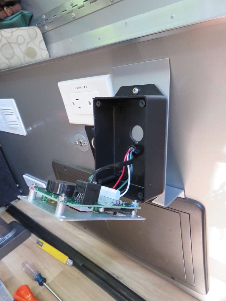
The Monitor:
Now the cool stuff begins. The monitor is installed on the bulkhead wall beneath the front table. I fashioned a nifty little bracket, to push the bottom of it out from the wall just a bit. I figured this will make the monitor just a little easier to see and use. A few holes were drilled, and the next thing you know, we had wiring out to the monitor. I then made the connections to the shunt in the battery box, then to the monitor, put the little fuse in place...success! The Trimetric was alive.
 |
| just a few extra connections here |

 |
| the little bracket actually makes quite the difference when viewing and using |
The Trimetric is a nice piece of engineering, but it does have a very complicated programming side to it. In fairness, after setting up three parameters, you can be off to the races. However, people buying this particular piece of kit are more interesting in programming the hell out of it. In a world full of simple user interfaces and mouse click convenience...this thing is old school. Not only is there the challenge of understanding of what the parameters mean, inputting those parameters is a primitive process. It does though invoke a reassuring sense of function over form. While it may not be friendly to program, the sophistication of its capabilities is very apparent, and in reality, that is why it was purchased in the first place. Even the language of the instruction manuals is very functional and to the point. No tech writer has polished this text for the masses, and did require several readings just to begin to understand what was going on.
As the controller was not yet installed, I just performed the basic set up, and let it monitor away. Right off the bat I was enthralled by the information it was gathering and outputting. Enthralled might seem a bit strong...but for the longest time I was mentally kidnapped by the glow of its flickering numbers.
The Rest:
Lots of odds and sods to this part. Panel combiner, controller, fuse holder, wiring...those little changes never seemed to end. Also, I wanted to do this after dark, to minimize the output of the panels. I remember saying to Dale that I had about another hour of work to do...boy did I ever under estimate that!
First I had to take the existing controller out of the picture, and that involved disconnecting the panels, then removing the controller from the front wall, to free up that needed space. As well, I then had to remove the existing wiring that connected the controller output to the distribution panel. This is where I discovered something that seemed a little out of the norm. During my research, in all the photographs or wiring schematics I had viewed, I had never seen the controller output wires go to any location other than directly to the terminals of the battery. In the Alto, the controller output was going to the distribution panel, through a 15 amp fuse. Clearly it works electrically, but is it the most effective method...that might be debatable. To me, it's like having those precious electrons take a rather meandering route to the battery. Does it really make a difference? That depends on how you look at it. I decided to follow what seemed to be a more common approach, and wired the solar controller output directly to the battery, through a fuse of course.
Next I needed to mount the solar combiner, the new controller, and the new fuse block. I am using a Blue Sea ATC fuse distribution block as a solar combiner. On the roof of most solar installations, the panel wires feed into a combiner box, get consolidated into positive and negative wires, then make their way to the controller, usually through a fuse. Our combiner is installed by the controller. Each panel is now fused, which provides a level of protection from each other, should one ever short circuit, and from the other direction should the controller ever go all willy nilly. I can now disconnect the panels from the solar circuit altogether, and I have lots of room to accommodate additional panels in the future. From here, the combined output goes directly to the controller, using the larger 6AWG wire.


The controller was installed and the combiner wires connected. On the output side, the negative wire goes directly to the Alto side of the shunt on the battery, so that the monitor can keep track of the solar input getting to the battery. The positive wire first passes through a MAXI fuse block on its way directly to the battery positive. The fuse block provides another layer of protection between the controller and the battery. All this is based on my view of what I think are some of the better solar installations that I have seen. I may have a bit of overkill here, but no harm done.


Final connections at the battery, and we are ready. One problem though, it is now pitch dark, and the solar is producing nothing. I left the combiner fuses out, and waited until the morning to see if the whole shebang actually works.
Next morning the fuses went in, the panels were already producing power, the controller was talking to the monitor and sweet electrons were flowing to the battery. Nice!
Now to fully program the Trimetric to manage the controller. Not to go into it completely (those really interested can download all the Trimetric documentation) but essentially you program the Trimetric monitor to manage the charging performed by the controller. Remember the concept mentioned earlier about tailoring the charging profile to the manufacturers specs, this is the time where that comes into play. Bogart has made this a little easier by creating several built in profiles that will populate the parameters needed, based on the different manufacturers specs. I found the Trojan 12 volt profile, and input it where required. This then populates the various charging voltages, amperages and timings accordingly. I discovered on the Trojan site that each of their batteries can have different charging specs, so I downloaded the spec sheet for our battery, and then fine tuned the parameters as needed. Trojan Battery has an excellent web site, and it is used as a knowledge base by many.
As the Trimetric can communicate with the controller, there is a smorgasbord of solar charging information available to monitor and review. I now know exactly what charging phase the controller is currently in, in addition to being able to know exactly the amperage output of the panels themselves. That is just the tip of the information iceberg. One of the first activities I will be doing as well is an energy audit of all things 12 volt. From this, I can then better guess at what our daily power consumption really is, and who the energy hogs are.
At the end of all of this, we now have a solar set up that monitors and charges our battery exactly to Trojan specs. Naturally there are variables, such as the hours of solar available in a particular day, but overall, I know that our new solar charging system will do a far better job of completely charging our battery than our grid power converter can. I see leaving it off grid power at home the majority of times, and letting the solar do its thing. Plugging in the night before we leave, to get the fridge cool using energy from the grid, will most likely be one of the rare times the Alto will be connected.
This mod ties in nicely with our future travel plans, where boon-docking will play be a big part. Even the past few years we have found ourselves preferring sites with no services, as generally, these are on the water, to us, a very desirable location. We have given ourselves excellent solar charging capabilities, and have ensured that any future expansion, however limited that may well be, will also be nicely accommodated. This was a fun project, and right up my alley, because for me, the Alto is not only about camping, it is also about modding, which is definitely a big hobby of mine.
Part 3 of this saga details the energy audit for our Alto.

I've been contemplating this mod as well. Thanks for sharing this.
ReplyDeleteHi Rufus,
ReplyDeleteSo far, I have been very pleased with the performance of the upgrade. I plan to keep an eye on how it does, and will post an update.
Hope all is well with you and Marla.
Terrific program for installation. I might be a few tools short to do all this. One more complication would be a new lithium ion battery
ReplyDeleteYes...a lithium battery introduces a whole new charging paradigm, but it seems from a performance perspective, well worth the effort.
Delete